Microcontroller Arduino Project Simple Monitoring System ECG. In this time we will discuss about Arduino Project.In arduino project we will try to use ECG with microcontroller arduino.
In Indonesia, Heart disease was becoming a big disease which health killer people for many years.World Health Organization (WHO) research also shows that the most people was dying due to heart disease. Therefore, This disease can not be taken lightly. Hence, most health care equipment and monitoring system are designed to keep track the disease. Most of health practices and guidelines was suggesting that ECG signal to be analyzed and monitoring at the initial stage of health assessment as a step of prevention too. Because we talk about monitoring system with arduino we must tutorial arduino and system in first
Project arduino in this article will show heart beat in computer with serial communication. this project will give you base example, how to use ECG with arduino. So, you can implementation this article to finish your project where use ECG with arduino.
An ECG Sensor with disposable electrodes attaches directly to the chest to detect every heart beat. The electrodes of ecg sensor will conversion heart beat to electric signal. ECG Sensors is very light weight, slim and accurately to measures continuous heart beat and give rate data of heart beat. This device always use by trained doctor and medical assistances.
Electrodes of ECG Sensor have 3 pins and connected by cable with 30 inches in length. It is make ECG sensor easy to conected with controller and placed at the waist or pocket. In additional, the plug-in for the cable is a male sound plug which will make the cable to easily removed or inserted in to the amplifier board.


The sensor assambled on an arm pulse and a leg pulse. All of every sensor electrodes have methods to assemble in body. So, training and tutorials are needed for user. You can choose type of electrode to measure heart beat.
In project which we will make small ECG system with arduino as a controller, To make ECG system we need in general:
- ECG / EKG electrode 3 piece
- Cable like sound plugin for ECG / EKG
- Arduino with USB Cable to download program
- Board convert heart beat to electric signal
- Computer with base GUI operating system, you can choose operating system to make program and implementation arduino with other operating system
- Arduino Editor and compiler (If you don't have you can download in https://www.arduino.cc/en/Main/Software). You can choose editor depent of your operating system. In arduino site, when article was made, there are three arduino editor for three operating system i.e WINDOWS, MAC OS and LINUX. Don't forget to choose editor in accordance with the operating system and bit of operating systems(32-bit or 64-bit).
- When we use arduino hardware in operating system. The system of operating system will request driver to run arduino device. So you must install driver for arduino device, you can download driver from official website http://www.ftdichip.com/Drivers/D2XX.htm or http://www.ftdichip.com/Drivers/VCP.htm
Specification of cable from electrodes ECG Clamp to AD8232 (Heart Rate Monitor). Lead wire which use for connecting electrodes ECG to AD8232 with TENS, EMS or other have low medium frequency therapy devices:
- Cable have durable, Highest intensity, flexiblelity and softly
- conductor with resistance≤1.2Ω
- Cable have Conductor material Tinsel7pcs
- Cable with length 1 m
- cable have sheathing material like PVC,PU
- cable with Plug jack input 3.5mm
- cable with storage temperature -30°C until +80°C
- cable with electrode disposable 4 pcs
ECG EKG electrode Sensor which connected with cable can assemble directly plug in to the board of AD8232. At AD8232 board have 6 pins which can be connected to arduino uno or mikrokontroller. In this project we will use arduino as controller.
The AD8232 is a based module with cost-effective board where used to measure activity of the heart with electrical signal. This electrical device will detect activity of heart which can be converted as an ECG or Electrocardiogram and maked output as an analog reading. The AD8232 Single Lead Heart Rate Monitor works as an op amp to assist obtain a clear signal from the PR and QT Intervals easily.
The AD8232 is a system project board of electronics with integrated signal conditioning block for ECG with applications for biopotential measurement . It is designed to amplify, extract and filter all of small biopotential signals from noisy conditions, such as those created by movement or action of electrode placement.
- AD8232 have Operating Voltage at 3.3V
- AD8232 have Analog Output
- AD8232 have Leads-Off Detection condition
- AD8232 have Shutdown Pin
- AD8232 have LED for Indicator
- AD8232 have 3.5mm Jack pin or 3 header for Biomedical Pad Connection
arduino
|
rate Monitor
|
3.3V
|
3.3V
|
pin 10
|
L0+
|
Pin 11
|
L0-
|
Analog 1 (A1)
|
Output
|
Gnd
|
Gnd
|
In this project I will use arduino uno as controller in the project system. Arduino uno in this project have function as ADC Converter. So that, ADC will read data from AD8232 send data to computer use serial communication and data will show in computer.
Before we starts to make program arduino advisable we must know about ECG.
ECG SIGNAL PARAMETER

The figure above display of standard one cycle ECG signal from a heart beat. From the figure one cycle consist of P wave, QRS wave until T wave. P wave offers benefit information about the propagation time of the impulse to both atria. Then, follow with a flat trend called with the PR segment which is in consequence of propagation of the electric impulse from atria to ventricles. And follow with QRS complex wave which you can look in above figure. Q,R and S complex contains of three small wave i.e small Q wave, the high R wave and the small S wave. The QRS complex give information about the ventricular systole in consequence of the impulse propagation to the ventricles (Q wave), whereas the transmission to the whole tissue is caused by the R and S wave. The QRS complex provides information about fibbrillations and arrhythmias, it can be helpful to analyze heart attacks. And then ST interval, it is following by the S wave and including with the T wave, it can point out the ischemia occurances. It represents the period during which ventricles are contracting, which is the last stage of the heart cycle. The T wave permits one to have information about the cardiac hypertrophy, heart attacks, and ischemia. Moreover, others parameters, such as the QT interval, allow soecific further pathologies to be characterized. Finally, the ECG signal ended with a small peak, U wave.
Table Normal ECG Parameters
Phase
|
Duration
|
Amplitude
|
P Wave
|
0.06-0.11
|
<0.25
|
PR Interval
|
0.12-0.20
|
-
|
PR Segment
|
0.08
|
-
|
QRS Complex
|
<0.12
|
0.8-1.2
|
ST Segment
|
0.12
|
-
|
QT Interval
|
0.36-0.44
|
-
|
T Wave
|
0.16
|
<0.5
|
Table Changes in parameters of ECG with Heart Disease
Abnormal
Parameter
|
Effect on
Heart
|
Short QT Interval
|
Hypercalcemia,
Hyperkalemia
|
Long
QT Interval
|
Hypocalcemia
|
Flat or inverted T waves
|
Coronary
ischemia, hypokalemia, left ventricular hypertrophy
|
Peaked
T wave, Long PR, QRS wide, QT short
|
Hyperkalemia
|
Prominent U waves
|
Hypokalemia
|
Increased
HR
|
Tachycardia
|
Decreased HR
|
Bradycardia
|
Increased
QRS
|
Bundle branch block
|
Increased PR
|
AV block
|
From the ECG parameters, analysis a Heart Rate Variability (HRV) of the ECG signal can be implemented. According to the parameters changes comparing to the normal parameters above, the system may predict which disease that the user potentially suffering from.
Requirement in this project:
- ECG / EKG electrode clamp 3 piece, with color RED (Right hand), YELLOW (Left Hand), BLACK (Right Foot)
- Cable like sound plugin for ECG / EKG
- Arduino UNO R3 with USB Cable to download program
- AD 8232 board convert heart beat to electric signal
- Computer with windows 7 32-bit operating system
- Arduino Editor and compiler compatible for windows 7 32-bit.
- Driver USB 2.0 Serial
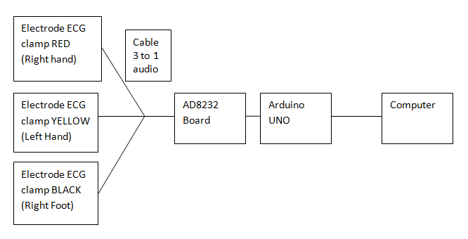
Make sure all of the requirements are installed appropriate with figure project. In figure, 3 three electrodes clamp connect to cable EKG. EKG cable connect to AD8232 board with 3.5 mm audio jack. Connect with cable board AD8232 to arduino like table AD8232 to arduino.Connect Arduino to computer with cable serial.
In editor arduino make program ECG to arduino:

In coding Arduino have two function in programming i.e:
- void setup(){}
- void loop(){}
Void setup is a function that was first executed. So, Usually a programmer arduino use this function to initials input, output device with putting initial the device which is connected to arduino like input output device.
void loop is a function that was executed repeatedly. Usually a programmer arduino use this function to make proccess programming or we can call core of programming.
The program is:
void setup() {
pinMode(10,INPUT);
pinMode(11,INPUT);
}
void loop() {
Serial.begin(9600);
if((digitalRead(10)==1)||(digitalRead(11)==1)){
Serial.println("Gagal");
}
else{
Serial.println(analogRead(A1));
}
delay(100);
Serial.end();
delay(100);
}
explanation coding of the program:
In arduino coding, we must we must pay attention to uppercase and lowercase or we can call arduino program case sensitive.
In void setup has two instructions program
- pinMode(10,INPUT);
- pinMode(11,INPUT);
pinMode is an instruction of arduino program to initial port. In this instruction, we initial pin 10 of arduino as an input
We initial pin 11 of arduino as an input
- Serial.begin(9600);
- if((digitalRead(10)==1)||(digitalRead(11)==1)){} else{}
- Serial.println("Gagal");
- Serial.println(analogRead(A1));
- delay(100);
- Serial.end();
This instruction is used to initial if we use serial communication with baud rate 9600
If pin 10 or 11 give value = 1 is execute if conditional, if pin 10 and 11 give value = 0 execute else conditional
Send message "Gagal" to serial communication.
Send value from analog input A1 to serial communication
Delay until 100 mili second
Close serial communication between arduino and computer.
If you want to check program from error you can click button compile like below:

If you wan to transfer program from computer to arduino you can click button verify like below:

If you want to see message error or success compile and upload program

Before transfer program to arduino, don't forget to choose type of board arduino:

In this case, I choose arduino/genuino uno because I use board arduino uno. choose tools ->port-> com X (x mean place of arduino com connect) and then click button verify, wait until you get message program success transfer
To get result from program click menu tools->serial monitor from will show. adjust baudrate of from same with arduino baudrate communication serial
You can look data from form serial monitor like below:
658
654
456
567
432
and etc.


0 komentar:
Post a Comment
Note: Only a member of this blog may post a comment.